 如何用树莓派驱动16x2 LCD
概述
向任何项目添加LCD会立即使它提高一个档次。本教程说明了如何使用6个GPIO引脚将廉价的HDD44780兼容LCD连接到Raspberry Pi。尽管还有其他方法可以使用I2C或UART进行连接,但这是直接使用裸机的最直接方法。
此技术:
允许使用廉价LCD
不需要任何 i2c驱动程序
不会窃取Pi上唯一的串行端口。
示例Python代码发送日期,时间和Pi的IP地址到显示器。如果您在无头模式下运行Pi,一眼就能确定IP地址非常方便。
要遵循本教程,您将需要
标准LCD 16x2 +其他功能
Pi T-Cobbler Plus,Pi Cobbler Plus用于模型B +/Pi 2或原始Pi补鞋匠
(2)半尺寸面包板
连接线
A Raspberry Pi(与所有26pin和40pin Pi兼容
您几乎可以将任何字符LCD与本教程-适用于16x1、16x2、20x2、20x4 LCD。它不适用于40x4 LCD
将补鞋匠连接到LCD
LCD
每当遇到带有16个连接器的LCD显示器时,最有可能使用HD44780控制器。这些设备提供相同的引出线,使其相对易于使用。 LCD使用并行接口,这意味着我们需要树莓派的许多引脚来控制它。在本教程中,我们将使用4个数据引脚(4位模式)和两个控制引脚。
数据引脚很简单。他们正在将数据发送到显示器(高/低切换)。我们将仅使用写入模式,而不读取任何数据。
寄存器选择引脚有两种用途。拉低时,它可以向LCD发送命令(例如移至或清除屏幕的位置)。这称为写指令或命令寄存器。当以另一种方式切换(1)时,寄存器选择引脚进入数据模式,并将其用于将数据发送到屏幕。
读/写引脚将被拉低(仅写)。 ),因为我们只希望基于此设置写入LCD。
启用引脚将被切换为将数据写入寄存器。
LCD引脚排列
接地
VCC- 5v不是3.3v
电位器的对比度调整(VO)
寄存器选择(RS)。 RS = 0:命令,RS = 1:数据
读/写(R/W)。 R/W = 0:写,R/W = 1:读(我们将不使用此引脚)
时钟(启用)。触发下降沿
位0 (4位操作中不使用)
位1 (4位操作中不使用)
位2 (在4位操作中不使用)
位3 (在4位操作中不使用)
第4位
第5位
第6位
第7位
背光LED阳极( +)
背光LED阴极(-)
在接线前,请检查LCD是否具有LED背光,而不是EL背光。 LED背光使用10-40mA的功率,EL背光使用200 + ma! EL背光灯通常价格便宜但无法使用,请确保不要使用背光灯,否则Pi会过载。一些带有LED背光的廉价LCD在LCD模块的背光上没有电阻,如果不确定,请在15针和5V引脚之间连接一个1Kohm电阻,而不是直接连接。 所有Adafruit液晶显示器都具有带内置电阻器的LED背光灯,因此您不需要额外的电阻器!
5v LCD vs 3.3v Pi
树莓派GPIO设计for3.3v,但我们的LCD是5v设备。 使用5v显示屏很好,但前提是我们要从Pi向外发送数据。我们不会在补鞋匠上使用3.3v电源轨,我们将显示器的 RW (读/写)引脚连接到GND,因为我们不希望显示器发送5v信号进入Pi。
别越过溪流!
接线图
首先,将补鞋匠电源引脚连接到面包板电源导轨。补鞋匠提供的+ 5.0V连接至红色条纹导轨(红色线),补鞋匠提供的GND连接至蓝色条纹导轨(黑色线)
为了将数据发送至LCD,我们将其接线为遵循
LCD的引脚#1接地
LCD的引脚#2达到+ 5V
引脚#3(Vo)连接到电位计的中间
4号针(RS)连接到补鞋匠#22
Pin#5(RW)接地
Pin #6(EN)连接到补鞋匠#17
跳过LCD引脚#7,#8,#9和#10
引脚#11(D4)连接到补鞋匠#25
Pin#12(D5)连接到Cobbler#24
Pin#13(D6)连接到Cobber#23
Pin#14(D7)连接到Cobber#18
针#15(LED +)转到+ 5V(红线)
针#16(LED-)接地(黑色线)
然后连接电位计,左引脚接地(黑线),右引脚接地+ 5V(红线)
以下是T-Cobbler Plus版本的草图:
》素描以26针的补鞋匠覆盆子Pi(v1,v2)
准备LCD
开始之前,请进行以下操作确保您有一个带0.1“公头的排针和一个10K电位器。所有Adafruit字符LCD都带有这些部件,因此您应该一切顺利。
大多数LCD都有顶部有16个针脚的条带,如果标头稍长,请将其断开,直到其正确的长度
接下来,您需要将接头连接到LCD。 您必须执行此操作,仅尝试“压入” LCD是不可行的!
首先连接补鞋匠的 5V 和 GND 线到面包板。然后将针脚#1,#2和#15,#16连接到面包板电源导轨,如图所示。背光应点亮。如果没有,请检查接线!
接下来,进行对比电位计,如上图所示,中间引脚连接到LCD引脚#3,另两个引脚连接到5V并接地。
扭转电位计,直到您看到LCD的第一行充满了方框。如果看不到方框,请检查接线!
完成 RS,RW,EN,D4,D5,D6,和 D7 引脚的接线,如图所示
就是这样!现在您可以运行Python脚本在屏幕上绘制文本了!
必要的软件包
最新的Raspbian
您的Pi必须运行最新版本的Raspbian。本教程使用Raspbian Stretch(2018年11月)编写。如果尚未为Raspberry Pi准备SD卡,请查阅我们的指南。安装完成后,请确保并运行以下命令以确保您的安装软件包是最新的。
下载:文件
复制代码
$ sudo apt-get update -y
$ sudo apt-get upgrade -y $ sudo apt-get update -y
$ sudo apt-get upgrade -y
安装pip3
pip3已与完整的Raspbian安装一起安装,但Raspbian Lite并未安装包括pip3,因此需要按如下所示进行安装。
下载:文件
复制代码
$ sudo apt-get install python3-pip $ sudo apt-get install python3-pip
安装adafruit-blinka
下载:文件
复制代码
$ sudo pip3 install adafruit-blinka $ sudo pip3 install adafruit-blinka
安装adafruit-circuitpython-charlcd
下载:文件
C opy代码
$ sudo pip3 install adafruit-circuitpython-charlcd $ sudo pip3 install adafruit-circuitpython-charlcd
Python脚本
以下代码可以下载到您的树莓派上,并运行以在LCD显示屏上获取机器的日期,时间和IP地址。
代码
下载:Project Zip 或 Drive_a_16x2_LCD_with_the_Raspberry_Pi.py | 在Github上查看
复制代码
from subprocess import Popen, PIPE
from time import sleep
from datetime import datetime
import board
import digitalio
import adafruit_character_lcd.character_lcd as characterlcd
# Modify this if you have a different sized character LCD
lcd_columns = 16
lcd_rows = 2
# compatible with all versions of RPI as of Jan. 2019
# v1 - v3B+
lcd_rs = digitalio.DigitalInOut(board.D22)
lcd_en = digitalio.DigitalInOut(board.D17)
lcd_d4 = digitalio.DigitalInOut(board.D25)
lcd_d5 = digitalio.DigitalInOut(board.D24)
lcd_d6 = digitalio.DigitalInOut(board.D23)
lcd_d7 = digitalio.DigitalInOut(board.D18)
# Initialise the lcd class
lcd = characterlcd.Character_LCD_Mono(lcd_rs, lcd_en, lcd_d4, lcd_d5, lcd_d6,
lcd_d7, lcd_columns, lcd_rows)
# looking for an active Ethernet or WiFi device
def find_interface():
find_device = “ip addr show”
interface_parse = run_cmd(find_device)
for line in interface_parse.splitlines():
if “state UP” in line:
dev_name = line.split(‘:’)[1]
return dev_name
# find an active IP on the first LIVE network device
def parse_ip():
find_ip = “ip addr show %s” % interface
find_ip = “ip addr show %s” % interface
ip_parse = run_cmd(find_ip)
for line in ip_parse.splitlines():
if “inet ” in line:
ip = line.split(‘ ’)[5]
ip = ip.split(‘/’)[0]
return ip
# run unix shell command, return as ASCII
def run_cmd(cmd):
p = Popen(cmd, shell=True, stdout=PIPE)
output = p.communicate()[0]
return output.decode(‘ascii’)
# wipe LCD screen before we start
lcd.clear()
# before we start the main loop - detect active network device and ip address
sleep(2)
interface = find_interface()
ip_address = parse_ip()
while True:
# date and time
lcd_line_1 = datetime.now().strftime(‘%b %d %H:%M:%S ’)
# current ip address
lcd_line_2 = “IP ” + ip_address
# combine both lines into one update to the display
lcd.message = lcd_line_1 + lcd_line_2
sleep(2)
下载代码
为了简单起见,将此文件放在您的主目录中。 wget命令使事情变得简单。
下载:文件
复制代码
$ wget https://raw.githubusercontent.com/adafruit/Adafruit_Learning_System_Guides/master/Drive_a_16x2_LCD_with_the_Raspberry_Pi/Drive_a_16x2_LCD_with_the_Raspberry_Pi.py $ wget https://raw.githubusercontent.com/adafruit/Adafruit_Learning_System_Guides/master/Drive_a_16x2_LCD_with_the_Raspberry_Pi/Drive_a_16x2_LCD_with_the_Raspberry_Pi.py
运行代码
以下命令将启动该程序,您应该会看到LCD显示屏上显示了日期,时间和IP地址。
下载:文件
复制代码
$ sudo python3 。/Drive_a_16x2_LCD_with_the_Raspberry_Pi.py $ sudo python3 。/Drive_a_16x2_LCD_with_the_Raspberry_Pi.py
在每次启动时显示时间和IP
拥有一个可以手动运行的脚本是一件好事,但花时间和时间来做不是很好Raspberry Pi启动时,显示屏上会弹出IP地址吗?这是使用初始化脚本完成的,该脚本在每次Raspberry Pi启动时都会运行我们的Python代码。
下载服务文件
以下命令将使您可以将lcd.service文件直接下载到您的Pi。 p》
下载:文件
复制代码
$ wget https://raw.githubusercontent.com/adafruit/Adafruit_Learning_System_Guides/master/Drive_a_16x2_LCD_with_the_Raspberry_Pi/lcd.service $ wget https://raw.githubusercontent.com/adafruit/Adafruit_Learning_System_Guides/master/Drive_a_16x2_LCD_with_the_Raspberry_Pi/lcd.service
下载:Project Zip 或 lcd.service | 在Github上查看
复制代码
[Unit]
Description=LCD date|time|ip
Requires=network-online.target
After=network-online.target
[Service]
ExecStart=/usr/bin/python3 Drive_a_16x2_LCD_with_the_Raspberry_Pi.py
WorkingDirectory=/home/pi
StandardOutput=inherit
StandardError=inherit
Restart=always
User=pi
[Install]
WantedBy=network-online.target
放置lcd.service文件
lcd.service文件需要复制到正确的位置,并且可以使用systemctl命令来启动|停止|启用服务。在启用此功能之前,最好先进行测试,因为系统上的路径可能存在细微差别。
下载:文件
复制代码
$ sudo cp lcd.service /etc/systemd/system $ sudo cp lcd.service /etc/systemd/system
测试lcd.service
下载:文件
复制代码
$ sudo systemctl daemon-reload
$ sudo systemctl start lcd.service
$ ps auxww | grep -i 16x2 $ sudo systemctl daemon-reload
$ sudo systemctl start lcd.service
$ ps auxww | grep -i 16x2

以下命令读取对服务文件的更新,启动lcd.service并确认该进程正在运行。如果脚本显示在“ ps”命令输出中,则说明您已正确完成所有操作,现在可以启用服务并重新启动。该服务应在启动时自动激活。
启用lcd.service
下载:文件
复制代码
$ sudo systemctl enable lcd.service $ sudo systemctl enable lcd.service
现在,每次启动时,LCD都会在启动时自动显示日期/时间/ip地址。这意味着您无需插入监视器即可知道何时可以访问Pi以及IP地址是什么。
时区
最后,但并非最不重要:我的Pi已配置了UT(通用时间)。我更喜欢根据我的时区(山)来查看时间。这是在Pi上为任何位置配置时间的方法。这是一次配置设置,将在两次重启之间保留。
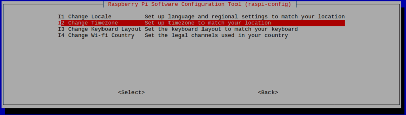
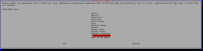
我们可以使用raspi-config轻松设置时区。选择以下内容:
本地化选项
更改时区
大陆/国家/地区
时区
运行raspi-config
下载:文件
复制代码
$ sudo raspi-config $ sudo raspi-config


责任编辑:wv
-
lcd
+关注
关注
34文章
4276浏览量
164050 -
树莓派
+关注
关注
113文章
1638浏览量
104727
发布评论请先 登录
相关推荐


 工商网监
工商网监
评论