 如何使用MATLAB GUI从基于Arduino的IR转速表读取RPM
步骤1:在MATLAB
打开您的MATLAB,然后键入命令:“ guide”
如果一切正常,将打开一个窗口供您设计布局。如果无法获取该窗口,请检查您的MATLAB安装中是否包含该模块。我的MATLAB版本是R2012b,安装了默认设置和软件包。
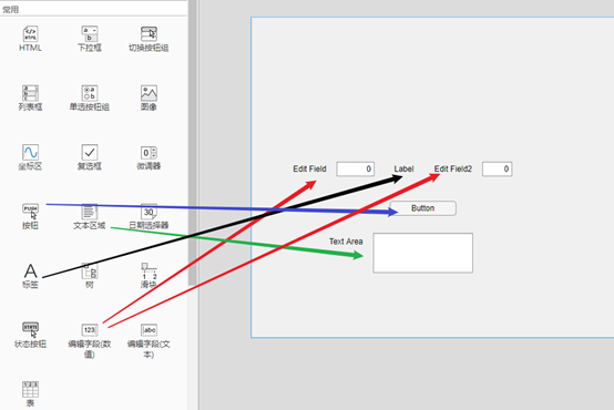
让我们假设您在输入“指南”后会感觉很好。放置窗口组件如下:
-1切换按钮
-2静态文本
按图片所示排列布局(实际上,布局要只要您易于使用和阅读,就可以通过修改属性检查器中的“字符串”值来更改每个对象中的文本(任何您想要的内容)(选择对象-右键单击-属性检查器,或双击)
然后,保存该GUI图形文件。
步骤2:编写代码
ARDUINO代码
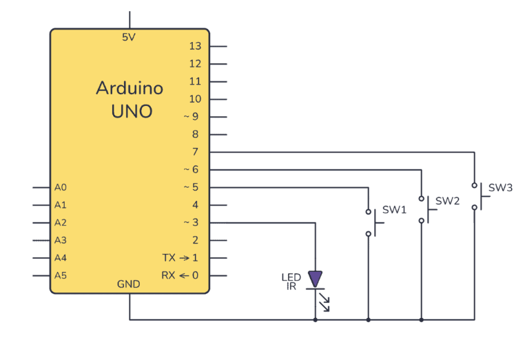
arduino的代码与您在此处可以找到的代码基本相同:https://www.instructables.com/id/Infrared-Tachomete 。..但因为这里我仅想要显示rpm值(而不是rps值以及所有的“ rps”和“ rpm”文本),所以我编辑了一些行(那些具有Serial.print()的行,因为以前该程序旨在显示读数在记事本式串行监视器上,但现在我们只需要rpm值即可输入到静态文本字符串中)。好的,为了方便快捷,我将代码复制到此处,您可以自行检查以与之前的代码进行比较。请记住,arduino代码的主要目的只是将值传递给串行comm,因此该程序仅作为示例,如果您有自己的程序将任何读取到的传感器的值打印到串行,然后忽略此操作即可。
int sensorvalue;
int state1 = HIGH;
int state2;
float rps;
float rpm;
long prevMillis = 0;
long interval = 100;
long currentTime;
long prevTime = 1;
long diffTime;
int sensorthreshold = 30; // this value indicates the limit reading between dark and light,
// it has to be tested as it may change acording on the
// distance the leds are placed.
// to see what number is good, check the sensorvalue variable value
// as printed out in the serial monitor
void setup()
{
Serial.begin(9600);
pinMode(13,OUTPUT); // assign pin 13 led as indicator because we cannot se the IR light
}
void loop()
{
sensorvalue = analogRead(0); // read from pin 0
if(sensorvalue 《 sensorthreshold)
state1 = HIGH;
else
state1 = LOW;
digitalWrite(13,state1); // as iR light is invisible for us, the led on pin 13
// indicate the state of the circuit.
if(state2!=state1){ //counts when the state change, thats from (dark to light) or
//from (light to dark), remember that IR light is invisible for us.
if (state2》state1){
currentTime = micros(); // Get the arduino time in microseconds
diffTime = currentTime - prevTime; // calculate the time difference from the last sensors meet-up
rps = 1000000/diffTime; // calculate how many rev per second - good to know
rpm = 60000000/diffTime; // calculate how many rev per minute
unsigned long currentMillis = millis();
// print to serial at every interval - defined at the variables declaration
if(currentMillis - prevMillis 》 interval){ // see if now already an interval long
prevMillis = currentMillis;
Serial.println(rpm); // this line is edited from the code in the prev instructable
}
prevTime = currentTime;
}
state2 = state1;
}
/* only for testing to determine the sensorthreshold value
delay(500);
Serial.println(sensorvalue);
*/
}
MATLAB代码
在MATLAB GUI布局设计窗口中,单击“查看-编辑器”(或在工具栏中找到没有手的纸和铅笔的图片)。将打开一个编辑器窗口,其中已经编写了一些代码,MATLAB为您编写了它们,没问题。只为切换按钮编写回调函数,其余代码可以保留不变。就我而言,我将切换按钮命名为OnOffToggle,因此编写代码的函数是函数OnOffToggle_Callback(hObject,eventdata,handles)。 rpmdata,所以我们只想将rpm数据打印到屏幕上即可。还有一件事,请确保在编写代码时将arduino连接到正确的COM端口。在这段代码中,我写了COM3,因为我将arduino连接到了COM3。
然后保存您的m文件。
下面是完整代码(仅编辑OnOffToggle_Callback函数):
function varargout = gui(varargin)
% GUI MATLAB code for gui.fig
% GUI, by itself, creates a new GUI or raises the existing
% singleton*.
%
% H = GUI returns the handle to a new GUI or the handle to
% the existing singleton*.
%
% GUI(‘CALLBACK’,hObject,eventData,handles,。..) calls the local
% function named CALLBACK in GUI.M with the given input arguments.
%
% GUI(‘Property’,‘Value’,。..) creates a new GUI or raises the
% existing singleton*. Starting from the left, property value pairs are
% applied to the GUI before gui_OpeningFcn gets called. An
% unrecognized property name or invalid value makes property application
% stop. All inputs are passed to gui_OpeningFcn via varargin.
%
% *See GUI Options on GUIDE‘s Tools menu. Choose “GUI allows only one
% instance to run (singleton)”。
%
% See also: GUIDE, GUIDATA, GUIHANDLES
% Edit the above text to modify the response to help gui
% Last Modified by GUIDE v2.5 14-Mar-2015 01:06:09
% Begin initialization code - DO NOT EDIT
gui_Singleton = 1;
gui_State = struct(’gui_Name‘, mfilename, 。..
’gui_Singleton‘, gui_Singleton, 。..
’gui_OpeningFcn‘, @gui_OpeningFcn, 。..
’gui_OutputFcn‘, @gui_OutputFcn, 。..
’gui_LayoutFcn‘, [] , 。..
’gui_Callback‘, []);
if nargin && ischar(varargin{1})
gui_State.gui_Callback = str2func(varargin{1});
end
if nargout
[varargout{1:nargout}] = gui_mainfcn(gui_State, varargin{:});
else
gui_mainfcn(gui_State, varargin{:});
end
% End initialization code - DO NOT EDIT
% --- Executes just before gui is made visible.
function gui_OpeningFcn(hObject, eventdata, handles, varargin)
% This function has no output args, see OutputFcn.
% hObject handle to figure
% eventdata reserved - to be defined in a future version of MATLAB
% handles structure with handles and user data (see GUIDATA)
% varargin command line arguments to gui (see VARARGIN)
% Choose default command line output for gui
handles.output = hObject;
% Update handles structure
guidata(hObject, handles);
% UIWAIT makes gui wait for user response (see UIRESUME)
% uiwait(handles.figure1);
% --- Outputs from this function are returned to the command line.
function varargout = gui_OutputFcn(hObject, eventdata, handles)
% varargout cell array for returning output args (see VARARGOUT);
% hObject handle to figure
% eventdata reserved - to be defined in a future version of MATLAB
% handles structure with handles and user data (see GUIDATA)
% Get default command line output from handles structure
varargout{1} = handles.output;
function currentEdit_Callback(hObject, eventdata, handles)
function currentEdit_CreateFcn(hObject, eventdata, handles)
% Hint: edit controls usually have a white background on Windows.
% See ISPC and COMPUTER.
if ispc && isequal(get(hObject,’BackgroundColor‘), get(0,’defaultUicontrolBackgroundColor‘))
set(hObject,’BackgroundColor‘,’white‘);
end
function OnOffToggle_Callback(hObject, eventdata, handles)
button_state = get(hObject,’Value‘);
if button_state == get(hObject,’Max‘)
set(handles.OnOffToggle,’String‘,’Stop‘);
drawnow;
i=2;
while i 》 1
rpmdata = serial(’COM3‘,’BaudRate‘,9600); % this Baud rate should be the same as that in Arduino code
fclose(instrfindall);
fopen(rpmdata);
b = fscanf(rpmdata);
set(handles.textCurrent,’String‘,b);
drawnow;
delete(rpmdata)
if get(hObject,’Value‘) == get(hObject,’Min‘)
break
end
end
set(handles.OnOffToggle,’String‘,’Start‘);
drawnow;
rpmdata = serial(’COM3‘,’BaudRate‘,9600);
fclose(rpmdata);
end
步骤3:运行Rpm Reader
完成代码后,连接arduino,然后转动旋转并运行程序(编辑器或布局编辑器窗口上的绿色三角形类似游戏的按钮)。程序的一个窗口将会出现(我的如图所示),单击切换按钮,您将在那里看到车轮的当前转速。
责任编辑:wv
-
matlab
+关注
关注
175文章
2922浏览量
228432 -
Arduino
+关注
关注
184文章
6427浏览量
184826 -
RPM
+关注
关注
0文章
44浏览量
17639
发布评论请先 登录
相关推荐
如何设置Arduino IR发射器电路
读取AD2S1210的速度寄存器,得到的速度值有±200rpm误差且呈正弦波动怎么解决?

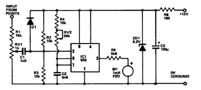
采用555定时器的转速表电路分享
使用MATLAB App Designer制作一个带GUI的加法计算器
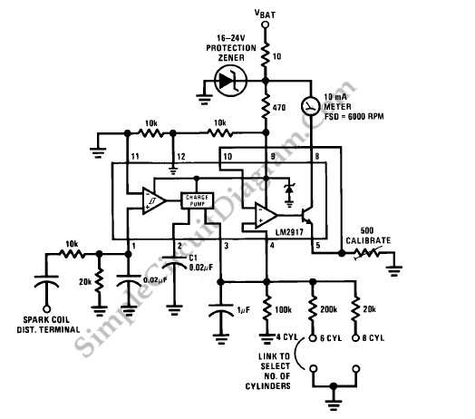
基于LM2917的汽车转速表电路
用于精确读数的Arduino转速计电路
什么是汽车转速表 转速表有什么作用
如何制作基于Arduino的IR接收器?
如何让转速计工作以反馈到PID循环中?


 工商网监
工商网监
评论