 交互式无接触灯的制作
第1步:我们需要什么
电子产品:
1。 2 x 22M欧姆+电阻器 (电阻值越大,传感器反应越远,我个人使用22M欧姆,获得可用数据的最小值为10M欧姆)
2。 3x 330欧姆电阻
3. 电线
4。 乙 readboard
5 即可。 电路板(我的铜条连续不断)
6。 多个常见的阴极RGB Leds (我使用8,但你可以或多或少取决于你想要多少光)
7。 铝箔
8。 Cling wrap
9。 Arduino Uno
10。 录像带
案例:
1。 Wood 我使用的是50 x 50 x 1.8 CM MDF(你可以使用任何东西。这取决于你想要的效果和你可以使用的工具)
的 2。 亚克力有机玻璃我使用50 x 50 x 0.3 CM(或任何其他透明/半透明材料,如宣纸)
3。 砂纸(细砂纸)
4. 木胶
5. 胶合板(可选)
6. 丙烯酸胶
工具:
剥线器
烙铁+锡
Stanley刀
钻
锯(我用过台锯)
第2步:原型设计:
现在我们有了一切,我们可以开始制作原型,看看它是如何工作的:
准备工作:
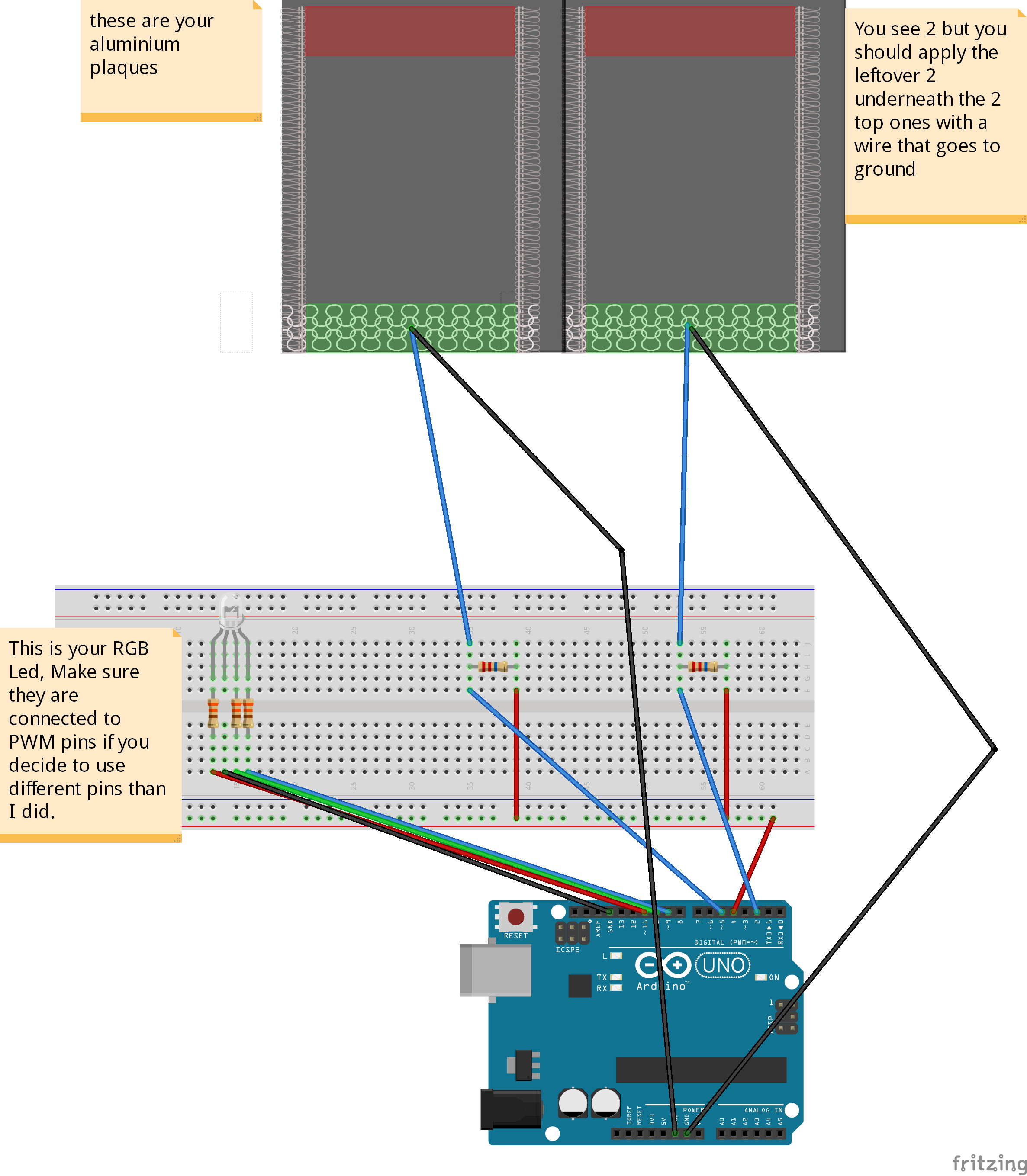
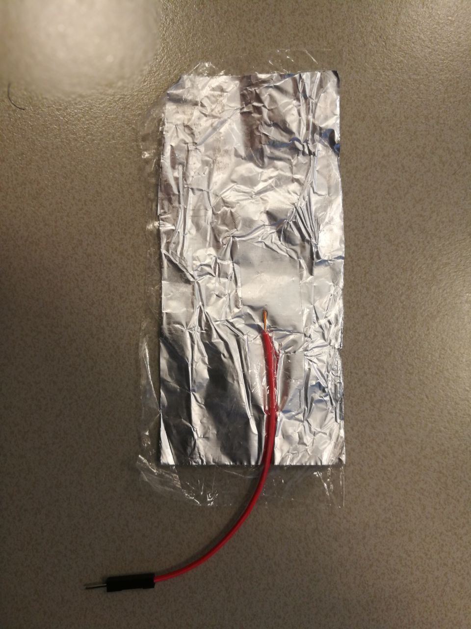
从铝箔上切下4个矩形(我的大约10厘米乘5厘米),将它们用保鲜膜包裹起来,以防止它们直接接触并将电线粘在铝箔上。我只是在箔上剥了一个剥离的末端(只要它们保持接触)。
为了确保铝是安全绝缘的,我用保鲜膜包好并在纸之间熨烫(只需几秒钟)所以它没有完全融化。)
然后设置电路,如图所示。
引脚4用作两个传感器的发送引脚,而接收引脚是引脚2和5.您可以使用多个发送引脚,但由于它们不是完全同步而导致故障。
在将所有内容焊接在一起之前使用此设置进行调试,以确保一切真正按预期工作。
步骤3:代码:
现在我们拥有一切,我们可以开始调试传感器了。
要使用我的代码,你应该从Arduino下载电容感应库并按照参考页面给出的指示进行安装:点击我
代码:(我不是非常适合编码,所以如果你知道如何更好地做,请做)
#include //import the code library
CapacitiveSensor cs_4_2 = CapacitiveSensor(4,2); //Send pin = 4, receive are 2 and 5
CapacitiveSensor cs_4_5 = CapacitiveSensor(4,5);
const int redPin = 11;
const int greenPin = 10;
const int bluePin = 9;
const int numIndexR = 10; // array size
const int numIndexG = 10;
int colorR = 0;
int colorG = 0;
float colorB = 0;
int indexR [numIndexR];
int posIndexR = 0;
long totalR = 0; //it needs to be a long because the total of my array was to big for an integer.
int averageR = 0;
int indexG [numIndexG];
int posIndexG = 0;
long totalG = 0;
int averageG = 0;
void setup()
{
pinMode(redPin, OUTPUT);
pinMode(greenPin, OUTPUT);
pinMode(bluePin, OUTPUT);
for (int thisIndexR = 0; thisIndexR 《 numIndexR; thisIndexR++) { //sets the array to 0
indexR [thisIndexR] = 0;
}
for (int thisIndexG = 0; thisIndexG 《 numIndexG; thisIndexG++) {
indexG [thisIndexG] = 0;
}
colorR = 255; //turns on all leds colors
colorG = 255;
colorB = 255;
Serial.begin(9600);
}
void loop()
{
long start = millis();
long total1 = cs_4_2.capacitiveSensor(10); //Save the raw sensor data to a variable
long total2 = cs_4_5.capacitiveSensor(10);
if (total1 》= 4500){ //cap the sensor values to a usable maximum, this is not the same for every resistor value and also might differ a bit from environment to environment you might need to tweak this to your own needs.
total1 = 4500;
}
if (total2 》= 4500){
total2 = 4500;
}
totalR = totalR - indexR[posIndexR]; //this here creates an array that continuously adds a sensor output and produces the average.
indexR[posIndexR] = total1;
totalR = totalR + indexR[posIndexR];
posIndexR = posIndexR + 1;
if (posIndexR 》= numIndexR){
posIndexR = 0;
}
averageR = totalR / numIndexR; //we use the average instead of the raw data to smooth out the output, it slows the process down slightly but it also creates a really nice smooth flow.
totalG = totalG - indexG[posIndexG];
indexG[posIndexG] = total2;
totalG = totalG + indexG[posIndexG];
posIndexG = posIndexG + 1;
if (posIndexG 》= numIndexG){
posIndexG = 0;
}
averageG = totalG / numIndexG;
if (averageR 》= 2000 ){ // we don‘t want the leds to constantly changes value unless there is input from your hand, so this makes sure all lower environmental readings are not taken into account.
colorR = map(averageR, 1000, 4500, 255, 0);
}
else if (averageR 《= 2000){
colorR = 255;
analogWrite (redPin, colorR);
}
if (averageG 》= 1000 ){
colorG = map(averageG, 1000, 4500, 255, 0);
analogWrite (greenPin, colorG);
}
else if (averageG 《= 1000){
colorG = 255;
analogWrite (greenPin, colorG);
}
if (colorR 《= 125 && colorG 《= 125){ //B works a bit different because I only used 2 sensors so I mapped B on both sensors
colorB = map(colorR, 255, 125, 0, 127.5) + map(colorG, 255, 125, 0, 127.5);
analogWrite (bluePin, colorB);
}
else{
colorB = map(colorR, 255, 125, 127.5, 0) + map(colorG, 255, 125, 127.5, 0);
if (colorB 》= 255){
colorB = 255;
}
if (colorB 《= 0){
colorB = 0;
}
analogWrite (bluePin, colorB);
}
Serial.print(millis() - start); //this is for debugging purposes
Serial.print(“ ”);
Serial.print(colorR);
Serial.print(“ ”);
Serial.print(colorG);
Serial.print(“ ”);
Serial.println(colorB);
delay(1);
}
这段代码的作用是从传感器中提取原始数据(这些数据总是会略微不稳定,因为影响传感器的所有不同因素)并且它将原始数据连续地放在一个数组中,当数组达到最大值(在我的情况下为10)时,它清除最后一个值并添加一个新值。每次添加一个值时,它都会计算平均值并将其放入一个新变量中。此平均变量用于将值映射到0到255之间的值,这是我们写入RGB引脚以增加每个通道亮度的值(通道为R G和B)。
现在,如果您将代码上传到arduino并打开串行监视器,当您将手悬停在每个传感器上时,您应该看到RGB值较低,而且LED的浅色也应该更改。
步骤4:现在为案例:


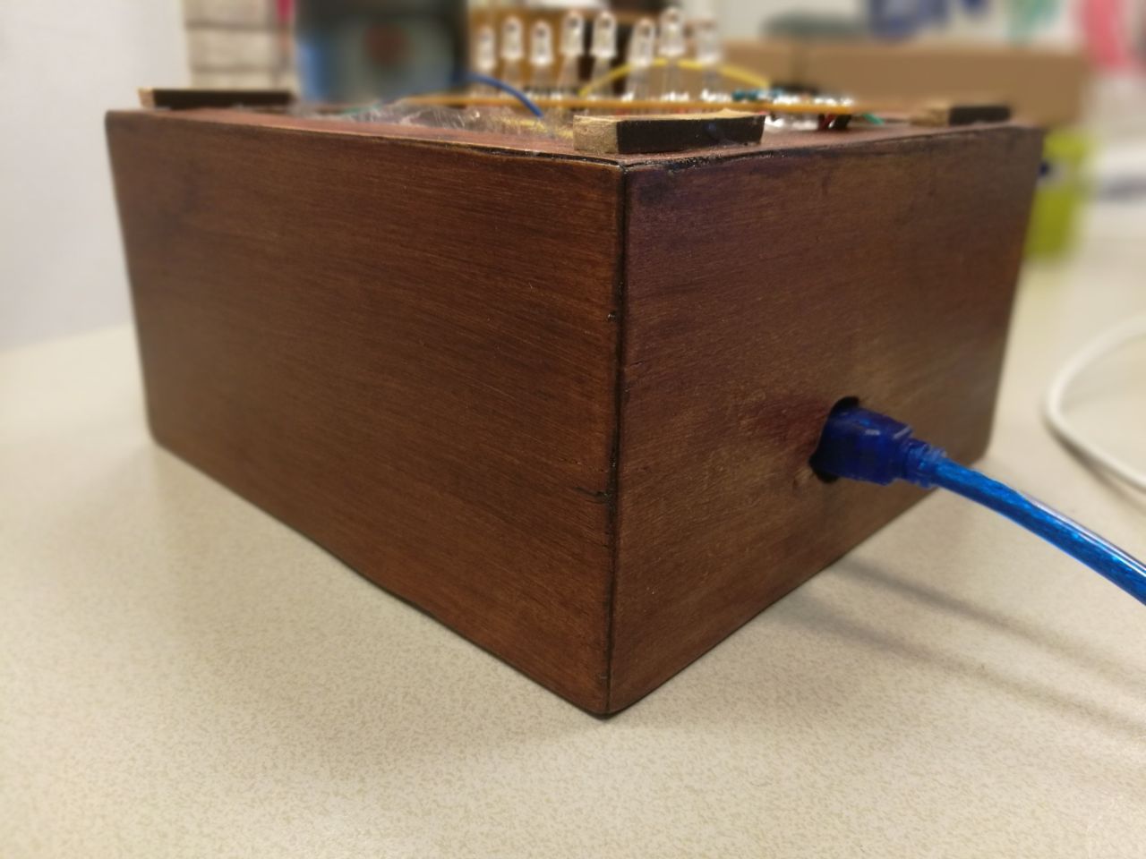
案例:我使用我大学提供的工具制作了这个案例,因此这个工作流程并不适用于所有人。然而,没有什么特别之处,它需要一侧的孔让USB端口适合穿过,但除此之外它只是一个敞开的顶盒。
尺寸如下:
15 x 15 CM用于透明顶部
和
15 x 8 CM用于木制基地(木材的厚度对我来说是1.8厘米)。
我用台锯将MDF板切成我需要的正确尺寸(这是4个面板15 x 8 CM和1 15 x 15 CM接地面板),之后我将角切成45度角。我使用木胶和夹子(让它至少干燥30分钟)粘在一起的所有部件,我使用相同的程序用于树脂玻璃,但使用特殊的锯片。
其中一个木质边应该在arduino USB插头高度的中心有一个孔,以便插入arduino。
我完成了单板的基础。我把它切成比每边的表面略大的碎片。
我粘上它,然后将它夹在每一边30分钟(更好的是单独做,所以你确保它不会滑动干燥之后,我将切掉的东西切掉了。
我用Acryl特有的胶水粘在一起称为Acryfix。
请注意,如果你使用丙烯酸树脂胶,胶水稍微溶解有机玻璃,因此尽可能精确和快速(它在几分钟内干燥,但在几秒钟内暴露在空气中)。
为了完成盖帽,我用喷砂机擦拭了立方体但你也可以使用细砂纸,只需要花费更多的时间使它看起来均匀。但要注意,如果你使用砂纸需要细粒度,并在结霜程序后将部件粘在一起(所以你不要破坏它意外地施加很大的压力)
为了确保盖子不会滑到太多,我在木制立方体的边缘粘了几个小木条。
第5步:最终结果应该是这样的:

第6步:焊接!
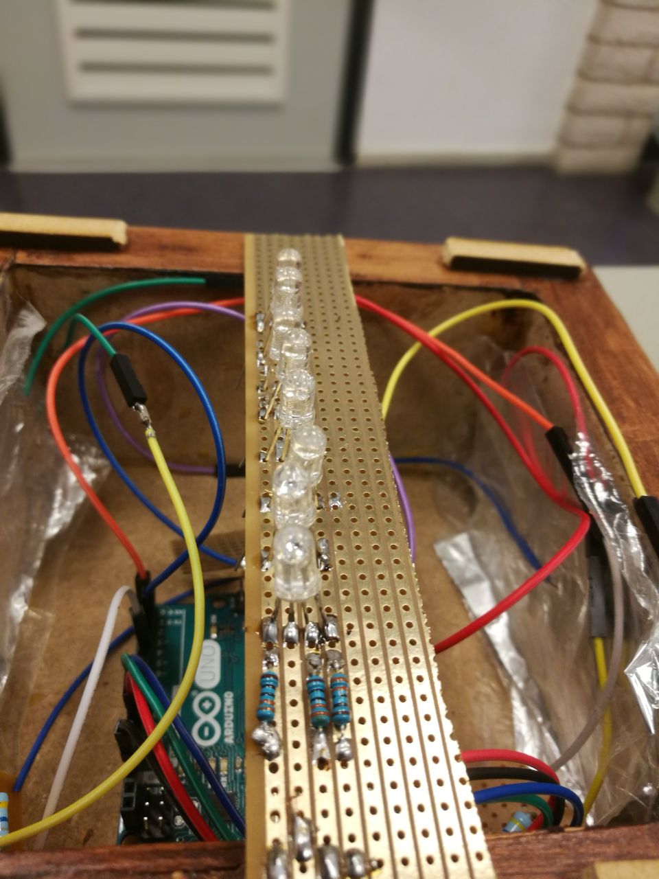

如果您有电路板,您可以使用面包板所具有的相同设置开始将所有部件焊接在一起。
我的电路板有连续的铜条,便于使用。
对于每个传感器,我切掉一个小方块,将电阻器和电线焊接到。
发送线(从引脚4到每个传感器的导线)按顺序焊接到一个单独的方形,1根导线进入引脚4.
我保留了一个长矩形,用于制作一个简易的LED条(测量它,使其适合帽的内部,但在基座的边缘)。你可以按顺序依次焊接LED(请记住图像我偶然焊接电路板错误一侧的LED和电阻,铜条应始终位于底面)。
将各个部件焊接在一起后,将它们装入外壳中。我没有将我的单根电线焊接在一起,所以如果需要我可以轻松地将它们更换。
时间让所有东西都融入基地:
这是最简单的步骤,arduino需要首先通过USB端口穿过背面的孔这个案子。现在添加传感器,确保传感器箔片两侧贴合木材,地面箔片直接贴在上面。当它完全适合时,将RGB LED插入右侧引脚(9,10,11)并让它靠在底座的边缘。
第7步:完成!
如果您已完成所有这一切,您现在应该有一个带电容式触摸颜色混合的工作灯。
-
传感器
+关注
关注
2525文章
48069浏览量
739977 -
Arduino
+关注
关注
184文章
6427浏览量
184824
发布评论请先 登录
相关推荐
市场前景向好,交互式人工智能提供商声通科技迎广阔发展空间
声通科技全栈交互式人工智能,助力企业智能化升级
以人才为核心,声通科技加速推动企业级全栈交互式人工智能发展
【爱芯派 Pro 开发板试用体验】+ 交互式抠图软件的实现
如何实现Pandas的DataFrame转换交互式表格
Mentor PADS Router交互式布线及相关设置教程
简易无接触温度测量与身份识别装置
Avatar Day:Omniverse 和 NVIDIA ACE 助力交互式数字人全流程开发

如何从解决方案开始 – 交互式信号链
ETH提出RecurrentGPT实现交互式超长文本生成
工业仪器3D交互式产品展示的亮点
Nexperia首创交互式数据手册,助力工程师随时随地分析MOSFET行为


 工商网监
工商网监
评论